Blowers for pressure
and Vacuum

+31 (0)79 3611 466 | info@sjerp.nl

Tips Side Channel Blowers

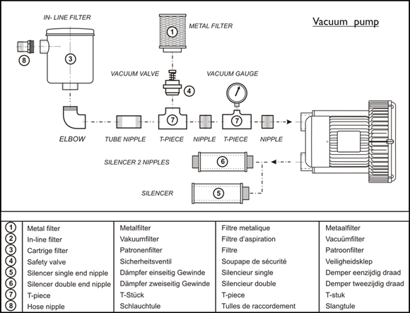
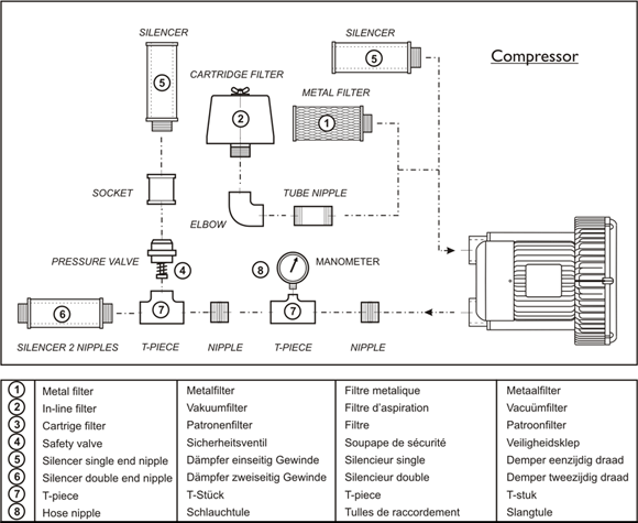
Various components are used in safety features for systems with vacuum pumps and compressors. In order to realise high operating reliability in your pump or blower, we will first show the safety mechanism for the side channel ventilator, implemented as a vacuum pump and as a compressor. This side channel ventilator must be protected against polluted air as well as overloading at excessive pressure. We will give you a few tips to support the safety features in your system.

Vacuumpomp example set-up

Vacuumpomp example set-up

Compressor example set-up

Compressor example set-up

Tips

  1. Always use a motor overload switch and never set it higher than the nominal current shown on the rating plate.
  2. A suction filter or an in-line cartridge filter prevents polluted air being extracted. The filter will need to be cleaned on a regular basis. This helps to prevent excessive pressure loss and potential overload.
  3. A safety valve, also referred to as a vacuum valve or over-pressure valve, protects your system against high pressure. A safety valve helps to prevent your system from overloading without interrupting the process. The set-up of the safety valve must be checked by measuring the inlet and outlet pressure using a manometer and by checking the motor current. Thus 100% of the ventilator's flow must pass through the safety valve. The vacuum valve can also be fitted with an extra filter so that environment air, which may contain incidental pollutants, does not damage the ventilator.
  4. A great amount of heat may be generated during the build-up of pressure or vacuum. Please ensure that the environment temperature does not exceed 40°C.
  5. When air is blown into or sucked from the open, noise dampers help to reduce noise pressure.
  6. Vibration dampers can help to reduce resonations in floors, walls and cabinets.
  7. By installing a manometer you can check the way in which your system operates and potentially detect polluted filters.
  8. If a permanent piping system is used, then one must implement expansion-compensators. Because the pipes warm up and cool down, they can introduce tension on the ventilator which may result in leakage or serious damage.
  9. Refer to the user manual for the service interval and include this in the installation's maintenance procedure.
  10. During the design phase, consider whether there is a risk of explosion (ATEX 153 zone) and whether the medium must be kept from the environment (gas-tight design).
  11. During frequency control, it is recommended to secure the motor using PTC’s. The high- frequency switching behaviour of the frequency regulator will always result in extra heat generation in the blowers' drive.

Videos

Here you will find a number of videos about construction, maintenance and use of our products.

>What is a side channel blower? and what is it 's performance?
What is a side channel blower? and what is it's performance?
February 13, 2020
In this video we make a cross-section of a side channel blower to explain the operation and the capacity. It gives you leads to make use of the wide control range.
Side channel blowers Tutorial 1: Fixed motor speed
April 22, 2020
What should I pay attention to when installing a side channel fan? How should I protect the side channel fan for reliable operation? The electrical and mechanical aspects for the professional.
Sjerp & Jongeneel Youtube - Blower Tutorial 2
Side channel blowers Tutorial 2: Variable frequency drives
15 March 2021

This tutorial is all about controlling the blower capacity. How to install and set up variable frequency drives for side channel blowers? This will be explained on the basis of three application examples and there will be put one into operation. This tutorial is full of helpful tips for the beginner and expert.

ELECTRICAL PARTS: 8153DB540 Dutair side channel blower; 17IN9560 ECO OPTIDRIVE HVAC IP66 Main switch 9.5A; 18PUR4G4S Shielded PUR 4 G 4 + (2 x 1,5); 18GM25EMC EMC glands M25 x 1,5; 18NM25EMC EMC gland nuts M25 x 1,5; 18PVC5G1 Shielded PVC data and signal cable 5G x 1,00; 18GM20EMC EMC glands M20 x 1,5; 18NM20EMC EMC gland nuts M20 x 1,5; Emergency stop red and green LEDs

MECHANICAL PARTS: 86TDB040040 Vibration dampers B 40/40 M8; 86060748 Bend Stainless Steel G2"; 8603232005 Socket Stainless Steel, G2" x 55 mm; 82FS231P201 Suction filter/ silencer G2"; 8603122010 Tube nipple Stainless Steel, G2" x 100mm; 86041220 T-piece Stainless Steel, G2"; 8604412005 Reduction ring Stainless Steel G2" x G½; 82MA100D4 Manometer 100mm, 0 - 400 mbar G½"; 86060928 Hose tail Stainless Steel G2"; 37SLSV84 Spiral reinforced hose G2"; 82DL305 Air Knife 305 mm, air slot 1 mm; hose clamps

Hello!

* Required
Send